KROnline logo goes here!
January 2003 (Volume 2,
Issue 1)
“Assembled” by Mark Langford
Making an Accurate
Instrument Panel
By Dave Mullins
First, make
a list of what equipment is required for VFR day/night or IFR whichever you
intend to fly. Add the equipment that you want to the list. Do not forget
switches, lights, and Headphone jacks. Second, make a template of the perimeter
of your panel. Get the entire instruments and radio sizes. Most can be gotten
out of your suppliers catalog or from the manufacturer’s website. Cut them out
of stiff cardboard. Position them on the outline template, moving them around
to get a design that makes you happy. Tape down the cutouts as a guide.
There
was a Panel Planner CD circulating the net. I do not know its whereabouts right
now. You could use this as a design tool, but, getting the instruments to line
up correctly is a hit or miss task and you need the Pro version to output a CAD
file.
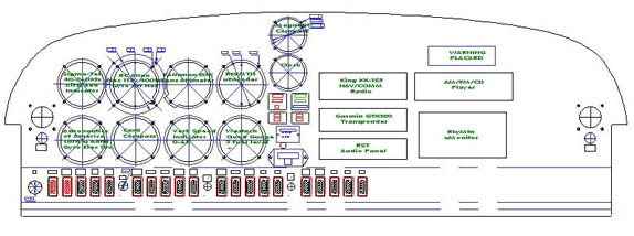
I
decided to use a real CAD program after fiddling with the panel planner
software. I used TurboCAD for this task. You can download a free 2D version
from http://www.turbocad.com. CompUSA
carries version 8 standard for $100. I will also make my file available to
those that need some where to start, at http://n323xl.iwarp.com/N323XLpanel.zip. Remember, if you use my file it is made to
fit my bird and is 4” taller and wider than stock dimensions. Just pull the
component cutouts to use.
After I
had drawn my panel out, I triple checked all the dimensions to make sure
everything was correct. I included both drilling guides and notations of hole
diameters. I used a plotter to print
out the finished drawing.
At this
time you could use spray adhesive to mount the drawing to your panel material (aluminum,
wood, fiberglass, etc). Center punch and drill all your holes next followed by
cutting all the square holes for the radio stack and other panel equipment
holes.
This
would be fine for most people, but I wanted my panel to be more accurate than
that. I located a machine shop with a waterjet cutter. A high-pressure stream
of water mixed with a tiny abrasive cuts aluminum like butter.
Hollis
Line Machine Company Inc 295 South Merrimack Road, Hollis New Hampshire, 03049
Tel: 603-465-2251
Fax:
603-465-2932
Their
OMAX waterjet cutter can handle 60” x 120” sheets up to 2.5” thick. I took the
CAD drawing over to Hollis and got a quote for the job. I asked them what type
of file format they needed, the reply was AutoCAD - DWG or DXF would work and
to remove all the notations and center marks. Just leave what you want cutout.
TurboCAD
is compatible with these two formats and a host of others, no problem there.
Depending on the complexity, your costs may vary.
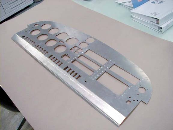
The job
was complete within a week. I wanted a couple of bends in the bottom of the
panel to stiffen the bottom edge. I went by another builder’s hangar to borrow
his eight-foot sheet metal brake. Well it tried to bend it but no go it was just
too much. The panel was cut from .063” 2024-T3. This material needs a radius
bend of 3 to 5 times the thickness. Now I needed a hydraulic press brake to
bend it.
Networking
with other builders, I found Greenfield Industries in Hollis. The owner was more
than helpful in bending my panel. I
have some sheer jobs for my fuel tanks I will take him next week.
I had
the rivet holes for the radio stacks cut slightly small and drilled them to the
correct sized drill bit. Even though
the waterjet is accurate to about .003” of an inch, I did not want too much
slop for the rivets.
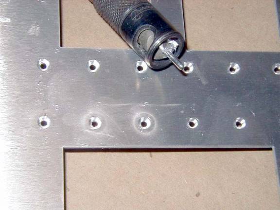
When they were drilled to the right size, I
used a microstop countersink drill for flush rivets.
I fitted
each of the instruments and other items I had. The only things needing slight
fitting were the indicator lights a circuit breaker switches.
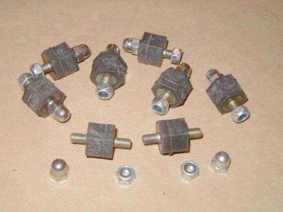
I have
two of my gyros already so the panel needs to be shock mounted. Now you could
by the aircraft ones for $8-10 each or you can do what I did and get them from
your neighborhood VW dealer for $2.50 each.
Thanks Mark Langford!
After
all the fitting of your instruments, clean the panel paint it with a coat of
zinc chromate primer, followed by your finish color. Mine will be ultra flat
black to cut down on any glare reflections.
There
are many ways to light your panel. What I chose to do is use electro
luminescent lights. There was a discussion on the Aeroelectric list a few weeks
back about it. So searching the web I found the stuff for aircraft at $300, too
rich for me. Continuing the search, I came across a kit for 5’ of 7/16” EL tape
and a 12V inverter for $45. Now that is more like it.
This kit
is made to modify your computer case and light up the inside after you cut a
window in your PC. Check them out at http://www.highspeedpc.com. I will see if
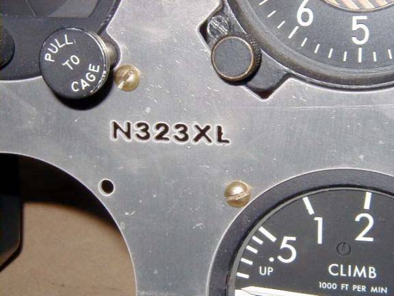
a dimmer can be attached to it. While
my panel was being cut, I included my N-number in the cutouts.
I will
take a small piece of the EL tape and put it behind the panel illuminating my
N-number. That will be a nice addition to my panel. Some letters and numbers
will not work this way but mine did.
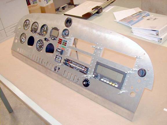
Here’s a
trial fit of the instruments I had at the time.
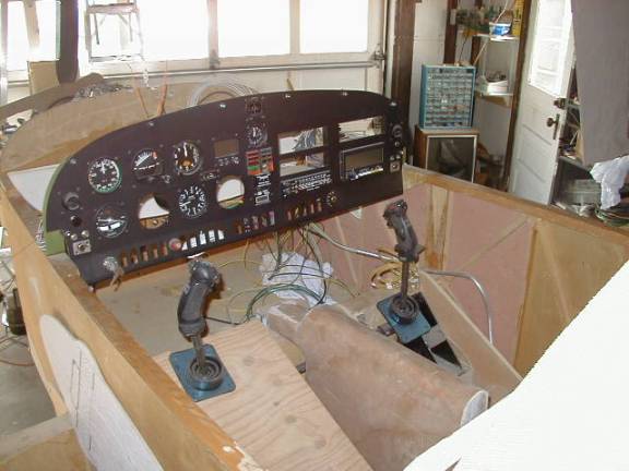
And the
finished panel in the fuselage.
Keep
tuned to my website for the latest updates
Dave
Mullins
Website –
http://www.n323xl.iwarp.com/
Email - mailto:N323XL@attbi.com
COAXIAL CABLES
By Jim Vance
The following is a list of
popular coaxial cables indicating their nominal impedance and their loss.
CABLE NOMINAL
IMPEDANCE ATTENTUATION OUTSIDE
In
ohms In decibels
per 100 ft. DIAMETER
RG 8 52 2.8 0.405 in.
RG 8 FOAM 50 1.9 0.405
RG 8 A 52 2.8 0.405
RG 9 51 2.8 0.420
RG 9 A 51 2.8 0.420
RG 9 B 50 2.8 0.420
RG 17 52 1.2 0.870
RG 17 A 52 1.2 0.870
RG 55 53
½ 5.5 0.216
RG 55 A 50 5.5 0.216
RG 55 B 53
½ 5.5 0.216
RG 58 53
½ 5.3 0.195
RG 58 FOAM 53
½ 1.8 0.195
RG 58 A 53
½ 6.0 0.195
RG 58 B 50 6.0 0.195
RG 58 C 50 5.3 0.195
RG 174 50 12.0 0.100
RG 174 A 50 12.0 0.100
RG 223 50 5.7 0.212
Belden 9913 50 1.4 0.405
Belden 9914 50 1.4 0.405
Decibels are a logarithmic
function, so the loss in watts increases exponentially as the numbers go
up. For example, if a cable has a 3 db.
loss per hundred feet, the power output to the antenna is ½ that of the
transmitter output. A 6 db loss would
result in only ¼ of the signal at the antenna; a 9 db loss is 1/8 the output of
the transmitter at the antenna; and a 12 db loss is 1/16 the output of the
transmitter at the antenna. At 12 db
with a 100 ft. long cable, the output of a five watt transmitter is only 0.31
watts.
The power loss in the
coaxial cable is linear along its length.
If your installation has 10 feet of cable between the transmitter and
the antenna, your loss would be 1/10 of the figures in the table. If your length is 25 feet, the loss would be
¼ of the figures in the table.
The larger diameter cables
have less loss, but are difficult to install because they require much larger
bend radii. And, they weigh a lot more.
Notice that for a given
diameter, FOAM dielectric coaxial cable is considerably more efficient than
solid dielectric found in most cables.
Foam coax can be purchased at radio or electronic outlets. Radio Shack coax is the very cheapest and
you aren’t getting a bargain.
The impedance of coaxial
cable is given as NOMINAL impedance, since variations in the manufacturing
process and installation can cause it to vary.
Therefore, 50 through 54 ohm cable will match and perform similarly.
The figures in the chart are
for a perfectly matched antenna. If
your antenna is not tuned properly, the coaxial cable then acts like a matching
transformer, and length and orientation becomes quite important. The result is a much greater loss in the
cable. For example, if you use a cable
with a 6 db. Loss per 100 feet and your antenna is mistuned so you have a 4 to
1 standing wave ratio, the power output to your antenna will be less than 10%
of the output of the transmitter. I
have measured installed antennas that had standing wave ratios of 10 to 1
! Even factory made airplanes are not
always perfect.
What you do to improve your
transmitted signal will similarly improve your received signal. Of course, ignition and other electrical
noise can affect the received signal, too.
To summarize, the best
coaxial cable for aircraft installations is RG 58 FOAM. It is also very important to have
your antenna tuned properly, especially if you are going to cover it up so you
can’t get to it later.
In the radio amateur crowd,
there are many technicians who work hard to get their coaxial cables and
antennas to perform perfectly. I’m sure
they would be willing to check your antenna for you. They would enjoy the opportunity to work on something different. And their charge is much less than going to
a radio shop.
I have a cheapy SWR meter
that I bought from Radio Shack years ago, as well as my industrial strength
Bird wattmeter than cost over $600.
Since you are interested in relative measurements as you tune your
antenna, the inexpensive unit would probably do the job. Radio Shack may still offer them. Interpreting what they tell you is an
education in itself, so it would be an advantage to have a radio type help you.
You can contact me at Vance@ClaflinWildcats.com.
Jim Vance
Letters
from
David Lininger:
In 1971 I graduated from
college and accepted a teaching position in Houston, Texas. After a couple of
months I started thinking about what I wanted to do with the huge amount of
money I was earning ($6,000 per year). Being single, and having no girlfriend,
I decided to do something I had always wanted to do: learn to fly. Accordingly,
I presented myself at Hobby Airport, checkbook in hand. A few months later I
received my Private Pilot’s License. During the year that I lived in Houston I
continued my reading of Flying, including Peter Garrison’s articles on
his homebuilt airplane, Melmoth. I assumed that building one’s own
airplane was not something normal people did.
A few years later I accepted
a Call to teach at Trinity Lutheran School, Potter, Wisconsin. One of the first
people I met there was the pastor, Rev. Ferdinand Timler. He mentioned that he
was building his own airplane, something called a KR1. He told me about the
EAA, and took me to my first EAA meeting in Manitowoc. We also spent several
days at Oshkosh that summer, and I started thinking about building my own
airplane.
I decided, after looking at
all the various planes there at Oshkosh, that I wanted a two place plane that
could use a VW engine. The next summer Rev. Timler and I again spent several
days at Oshkosh, and on one of those days I purchased a set of plans for the
KR2. The cost was reasonable, even by 1975 standards. Of course, all I got was
a little yellow booklet with a few drawings.
Over the next 20 years I
would take those plans out once in a while and think about building my own
airplane. Each time, though I would put them away, as other responsibilities
made their claims on my time and finances. I left Wisconsin in 1977. A wife was
added in 1983, and children in 1985 and 1986, along with a move to Missouri. In
1989, however, things started looking up. We purchased a building that had
originally been built to be a clinic in 1914. Sometime in the mid 1960’s it had
been moved to its present location, and about the time I was purchasing my KR2
plans a 3-car garage was built. The back garage, approximately 12 feet x 24
feet, was just begging to become an airplane factory. In 1993, therefore, I
insulated the garage, replaced the old door with an insulated one, and added
lights, a workbench, and a kerosene heater. I ordered a 4 x 12 piece of ¾ inch
particle board for my table, and on a vacation trip, visited Wick’s Organ for
the purchase of enough spruce to build the boat. A neighbor took the original
drawings and created a full-size side drawing, so that all I had to do was put
my wood between the lines and glue it together.
Yeah, right! Building those
two sides took me nearly two years, even with the full-size drawings. As those
who have built a KR know, there are very few 90º angles in the sides. I didn’t
count the gusset (corner) blocks, but there are many of them.
The summer of 1998 saw
another move, this time 100 miles away from that house in Concordia to 10 acres
in the Ozarks. No garage, no basement, no house, no buildings of any kind, in
fact. How does one build an airplane in that situation?
My solution was to purchase
an 8 x 12 storage building and to cut my particle board table (yes, I kept the
particle board) to fit in the shed. I used the 2x6’s that had been the forms
for the house’s slab to make the supports for the table. This table is actually
studier than the one I had in Concordia, probably because it is supported on
three sides by 2x6 supports nailed to the shed walls and by 2x6 legs on the
front, which are attached to a 2x6 that runs along the front.
Unfortunately, one of the
two sides I built in Concordia was damaged in the move, and I’ve been studying
the possible solutions to the problem. I built my sides per the original plans,
and I’m seriously thinking about just starting over and adding additional
length forward of the front spar and aft of the rear spar, a la KR2S. The
cheapskate part of me objects to the expense, though, and is arguing for simply
gluing some additional ⅝ spruce on the top and inside around the break.
Since the break is near the tail, the repair won’t be visible, and the plywood
skin will be on the outside and bottom. I’ll probably end up just cutting out
the broken piece and replacing it as a compromise.
I’d like to keep my KR
pretty much stock, with one major exception: I’m definitely going to widen the
cockpit! I got a chance to ride in Marty’s KR2 at Red Oak (thanks again, Marty)
and we were definitely a tight fit. Although I’m not much taller than Ken Rand
was, my wife, twin daughters, and the good cooks at church and school are all
making sure that I never again will see Ken’s weight!
So where do I go from here?
During the winter I’ll make up my mind about the damaged side, and in February
or March I’ll start doing whatever I decide to do. I’d like to get the boat
stage done before next winter. Of course, that means deciding whether to put
the skins on before or after the fuselage is formed! Then there is the suggestion
to make the sides vertical all the way, rather than to have them taper in at
the cockpit area. Decisions, decisions.
Comments, suggestions, and
visitors are welcome. Contact me at:
David Lininger
42 Rountree Rd
Urbana, MO 65767
(417) 993-0173